|
|
|
|
Imaging overturning reflections by Riemannian Wavefield Extrapolation |
Figures 4(a)-4(b) depict wavefields at ![]() and
and ![]() seconds from the exploding reflector moment, respectively. As expected, the wavefield originating on the overhanging salt flank dives and then returns to the surface (Figure 5). Other parts of the wavefield either propagate straight up to the surface, or propagate away from it and are not recorded. The imaged components of the recorded wavefield are those overturning to the surface at locations intersected by the coordinate system.
seconds from the exploding reflector moment, respectively. As expected, the wavefield originating on the overhanging salt flank dives and then returns to the surface (Figure 5). Other parts of the wavefield either propagate straight up to the surface, or propagate away from it and are not recorded. The imaged components of the recorded wavefield are those overturning to the surface at locations intersected by the coordinate system.

|
|---|
|
wo5,wo10
Figure 4. Wavefield from the overhanging salt flank at |
|
|

|
|---|
|
datCC
Figure 5. Recorded data at the surface. Overturning energy is recorded from |
|
|
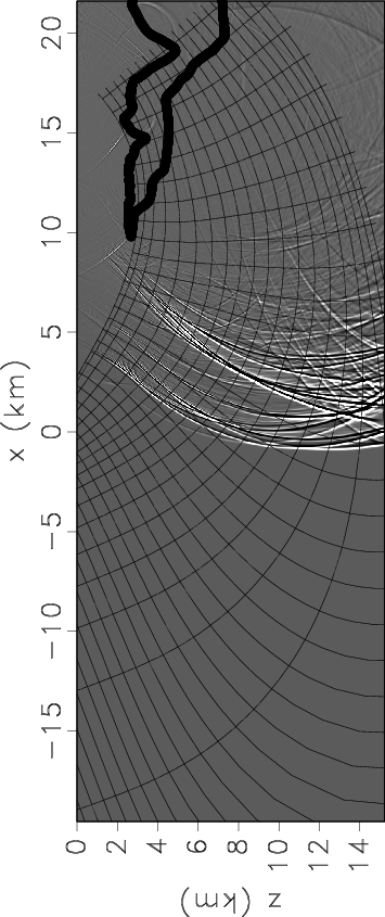
The overturned data collected at the surface are imaged in Riemannian and tilted Cartesian coordinates using the systems depicted in Figures 1(a)-1(b), characterized by coefficients ![]() and
and ![]() depicted in Figures 2(a)-2(b) and Figures 3(a)-3(b), respectively.
depicted in Figures 2(a)-2(b) and Figures 3(a)-3(b), respectively.


|
|---|
|
compRC1-F15,compCC1-F15
Figure 6. Migrated images using wavefield extrapolation in Riemannian coordinates with a Fourier finite-differences (F15) kernel. Panel (a) depicts the image in Riemannian coordinates, and panel (b) depicts the same image mapped to vertical Cartesian coordinates. |
|
|
Figures 6(a)-6(b) show the migrated image obtained by wavefield extrapolation in Riemannian coordinates. Panel 6(a) depicts the image in the Riemannian space, and panel 6(b) depicts the same image after mapping to vertical Cartesian coordinates. Both overhanging reflectors, on opposite sides of the salt body, are imaged correctly demonstrating successful imaging with overturning waves in Riemannian coordinates.


|
|---|
|
compRC2-F15,compCC2-F15
Figure 7. Migrated images using wavefield extrapolation in tilted Cartesian coordinates with a Fourier finite-differences (F15) kernel. Panel (a) depicts the image in tilted Cartesian coordinates, and panel (b) depicts the same image mapped to vertical Cartesian coordinates. |
|
|
Figures 7(a)-7(b) show analogous images obtained by extrapolation in tilted Cartesian coordinates. Imaging is performed using the same extrapolation as the one used for imaging in Riemannian coordinates. The only difference is the coordinate system, therefore all image differences are caused strictly by the coordinate system and not by the extrapolation or imaging operators.
Unlike for the preceding example, the overhanging salt flanks are not positioned correctly, as seen by comparing Figures 6(a) and 7(a). The reason for the inaccurate reflector positioning is the limited accuracy of the extrapolation operator at high angles relative to the extrapolation direction. While the Riemannian coordinate system has the flexibility to minimize the angle between the extrapolation direction and the direction of wave propagation, the tilted Cartesian coordinate system cannot do that, thus requiring wavefield extrapolation at high angles. In this example, modifying the tilt angle of the Cartesian coordinate system does not help since propagation at high angles occurs both in the vicinity of the reflector and close to the acquisition surface. Furthermore, the Riemannian coordinate system represents the natural direction of wave propagation, unlike the tilted Cartesian coordinate system which is artificial and has no physical relation to the propagating waves.
|
|
|
|
Imaging overturning reflections by Riemannian Wavefield Extrapolation |