|
|
|
|
Plane-wave Sobel attribute for discontinuity enhancement in seismic images |
|
|---|
|
sub
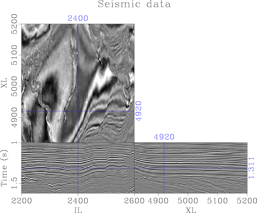
Figure 1. The Parihaka seismic data |
|
|
This image contains complex geologic structures, including multiple generations of faulting, meandering channel systems, and prominent unconformities (Figure 1).
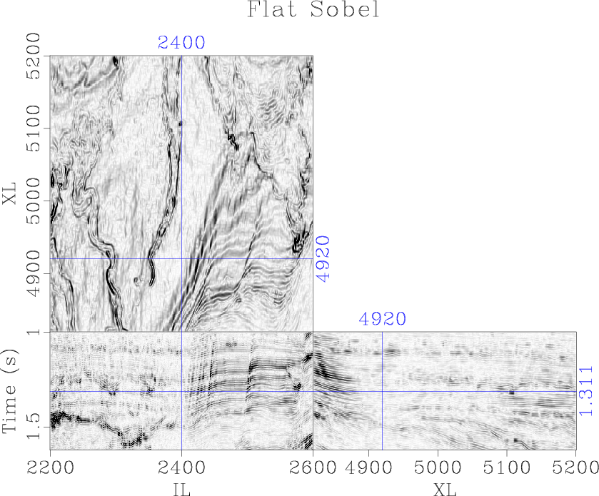
We first apply the traditional Sobel filter. This attribute enhances discontinuous geologic features, but also enhances dipping reflectors (Figure 3a).
In order to optimally enhance discontinuous features, it is important to orient the filter along local slopes. We compute the structural dip in the inline (Figure 2a) and crossline (Figure 2b) directions using accelerated plane-wave destruction (Chen et al., 2013). Using the local slopes, we apply structure-oriented smoothing to enhance seismic structures and attenuate noise without blurring geologic edges (Liu et al., 2010). We subsequently apply the proposed plane-wave Sobel filter and compute the magnitude of the inline and crossline plane-wave Sobel images. Discontinuous geologic features, most prominently faults, channels, and unconformities, are enhanced, revealing subtle details which would be difficult to interpret from the original seismic image (Figure 3b).
We compute a more segmented image by cascading another iteration of filtering to the Sobel image (Figure 3c). Alternatively the second iteration of Sobel filtering may be oriented not only along the dip of seismic reflections, but also the azimuth, using structural information derived from the original image (Figure 3d). We compute linear combinations of these inline and crossline images weighted by the cosine and sine of the azimuth. The local azimuth of the faults and channels corresponds to the orientation which creates the optimal image at each point. We find that the azimuth of the seismic expression of discontinuous geological features can be estimated more accurately by applying the azimuth scanning workflow to the Sobel filter image rather than the original seismic image. Faults and channels are further segmented in the cascaded image by automatically orienting the Sobel filter along geologic structures (Figure 3d).


|
|---|
|
idip,xdip
Figure 2. (a) Inline and (b) crossline reflection slopes computed using accelerated plane-wave destruction |
|
|


|
|---|
|
flat,sobel,sobel2,slices
Figure 3. (a) The traditional Sobel filter, (b) proposed plane-wave Sobel filter, (c) cascaded plane-wave Sobel filter, and (d) azimuthal plane-wave Sobel filter applied to the Parihaka seismic data |
|
|
|
|
|
|
Plane-wave Sobel attribute for discontinuity enhancement in seismic images |