|
|
|
|
Stacking angle-domain common-image gathers for normalization of illumination |
Two synthetic examples illustrate the method of stacking ADCIGs for illumination normalization.
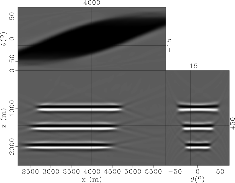
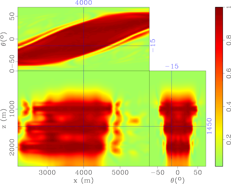
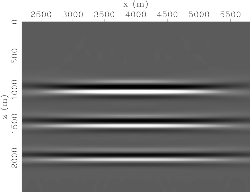
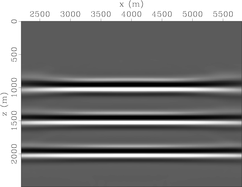
The first example involves a simple constant-velocity model with three reflectors. The reflecting interfaces are caused by density contrasts, which are chosen in such a way that all reflection coefficients for all reflectors and reflection angles are identical. A similar model was applied by Zhang et al. (2003) and Schleicher et al. (2008). The synthetic dataset is generated using Kirchhoff modeling. It includes 25 shots between 3,000 and 5,000 m, and range of offset is -3,000 to 3,000 m. PSPI wave equation migration is performed for generating ADCIGs (Figure 2(a)). The three reflectors can be found to have different folds caused by acquisition geometry. The parts that are not illuminated in ADCIGs do not all have zero values; some are occupied by noise or artifacts. Therefore, appropriate normalization when stacking all reflection coefficients of different reflection angles together must be ensured. The local similarity cube (Figure 2(b)) can provide normalization for stacking. By comparing equal-weight stacking and our method (Figure 3), we find that image amplitudes are improved, especially on the sides of the model, which are not entirely illuminated because of acquisition.
|
|---|
|
ppangtr-h,similtr
Figure 2. (a) ADCIGs for the simple synthetic example; (b) local similarity cube. |
|
|
|
|---|
|
stack,simistack
Figure 3. (a) Equal-weight stack; (b) stack normalized by local similarity. |
|
|
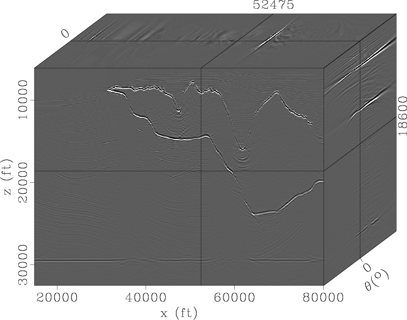
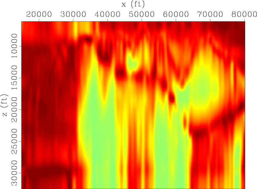
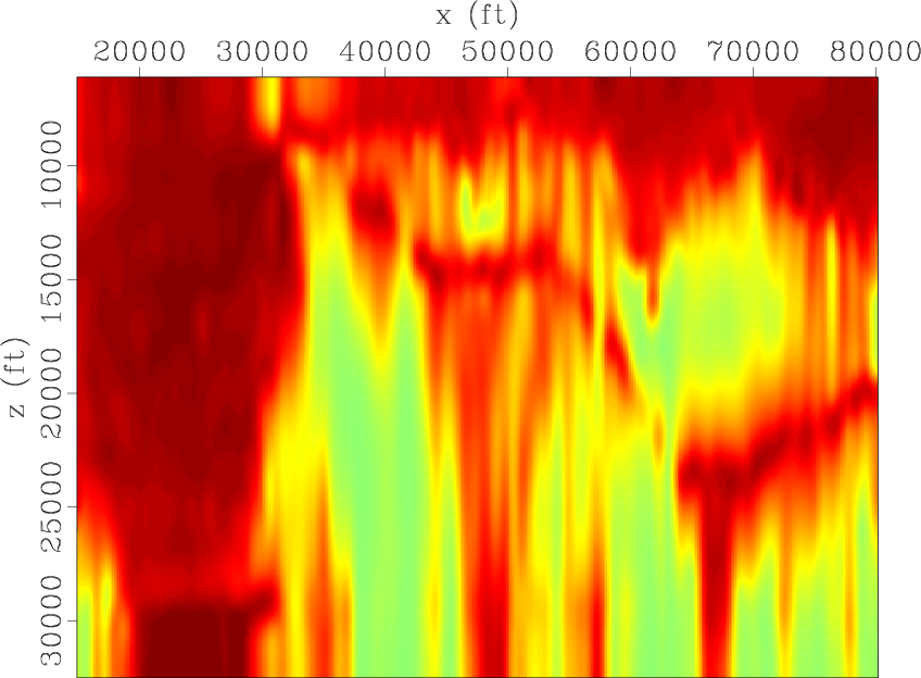
The second example involves the Sigsbee2A model (Paffenholz, 2000). This dataset is known to have illumination problems below the salt. Figure 4 shows the ADCIGs of Sigsbee2A model. Figures 5(a) and 6(a), respectively, show images of ![]() and
and ![]() reflection angles. Figures 5(b) and 6(b), respectively, show the local similarity cube of
reflection angles. Figures 5(b) and 6(b), respectively, show the local similarity cube of ![]() and
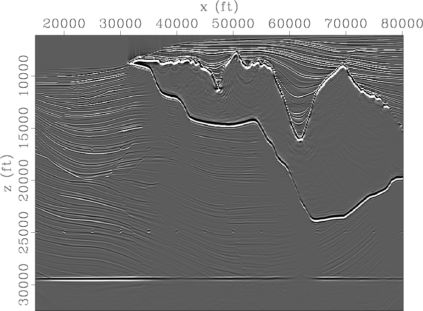
and ![]() reflection angles. Comparing local similarity cubes of different reflection angles, we can find that folds of local illumination are not equal for all image points. The folds are closely uniform in areas with simple structures, but differences can be found in complex media, such as in subsalt areas (Figures 5(b) and 6(b)). Figure 7 shows the result of equal-weight stacking, and Figure 8 shows the result of our method. With normalization, reflection coefficients are restored, such as below the salt (Figure 8). Our method's image beneath the salt is clearer than that of the conventional stacking method, and amplitude of the base line, with strong reflectivity at the bottom of the Sigsbee2A model, is more balanced. Note that fault and diffraction points below the salt become clearer after normalization using local similarity.
reflection angles. Comparing local similarity cubes of different reflection angles, we can find that folds of local illumination are not equal for all image points. The folds are closely uniform in areas with simple structures, but differences can be found in complex media, such as in subsalt areas (Figures 5(b) and 6(b)). Figure 7 shows the result of equal-weight stacking, and Figure 8 shows the result of our method. With normalization, reflection coefficients are restored, such as below the salt (Figure 8). Our method's image beneath the salt is clearer than that of the conventional stacking method, and amplitude of the base line, with strong reflectivity at the bottom of the Sigsbee2A model, is more balanced. Note that fault and diffraction points below the salt become clearer after normalization using local similarity.
|
|---|
|
angs
Figure 4. ADCIGs of the Sigsbee2A Model. |
|
|

|
|---|
|
ang1,simil1
Figure 5. |
|
|

|
|---|
|
ang2,simil2
Figure 6. |
|
|
|
|---|
|
sigstack
Figure 7. The image of Sigsbee2A using initial equal-weight stacking. |
|
|

|
|---|
|
sigsimistack
Figure 8. The image of Sigsbee2A using stacking with normalization by local similarity. |
|
|
|
|
|
|
Stacking angle-domain common-image gathers for normalization of illumination |